
Mono-cam Image Processing
Measuring exact distances and dimensions in an image is possible only if we know a parameter which has length dimension. This is a principle in image processing. In other words, since the camera depicts 3-D world on 2-D planes, information on the ratio of angles to distances is preserved but the distances and dimensions are lost with a measure freedom degree. For example, the image of an object with height of 1 meter and distance of 10 meters from camera is the same as the image of an object of 2 meters' height and distance of 20 meters from camera.
For any particular problem one should always insert one of these length parameters according to that problem. For example, in processing pictures of airplane cameras, height from the ground (measured by laser or radar rangefinder) or birds' velocity (measured by air sensors) can be inserted as a length parameter in the solution. But generally there are no more than 2 constant length parameters (suitable for the problem) for distance measurement and subsequently speedometer of the vehicles on the street:
- Height of the camera pole
- The constant width of license plates
Choosing each one of them determines the image processing algorithm in the next step. If height of camera pole is used as the pre-known parameter then the distance measurement and speedometer algorithm will be based on forming a right triangle as shown below:
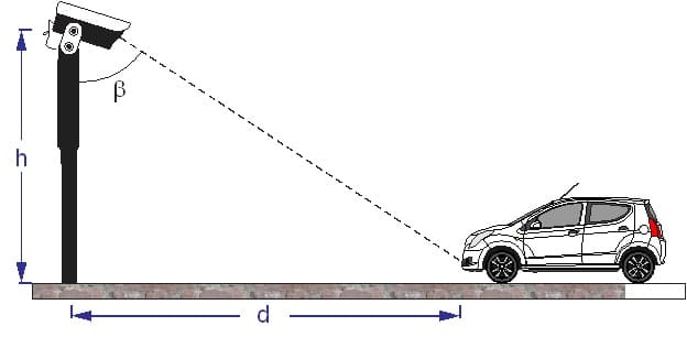
Thus if the location of the object is clear in the image and also the setup angle of the camera is known accurately then the distance of the object from the camera pole will be derived easily by forming the above right triangle. In the other method we exploit the fact that the image size is inversely proportional to its distance. Thus the vehicle’s plate’s size (which is equal and known for every vehicle) varies while the cars distance from the camera is changing. By knowing the plate size and the camera characteristics, we can compute distance from camera pole.Briefly, most important methods of mono-cam distance measurement and consequently speedometer can be summarized in the table below:
| Triangle method | Image size variation method |
| Essential parameter with length dimension is camera pole’s height. | Essential parameter is width of license plate. |
| Image processing is based on the object’s movement along Y axis. | Image processing is based on changing the object’s size along X axis. |
We will discuss each method in details in following chapters:
Mono-cam image processing based on trigonometric approach
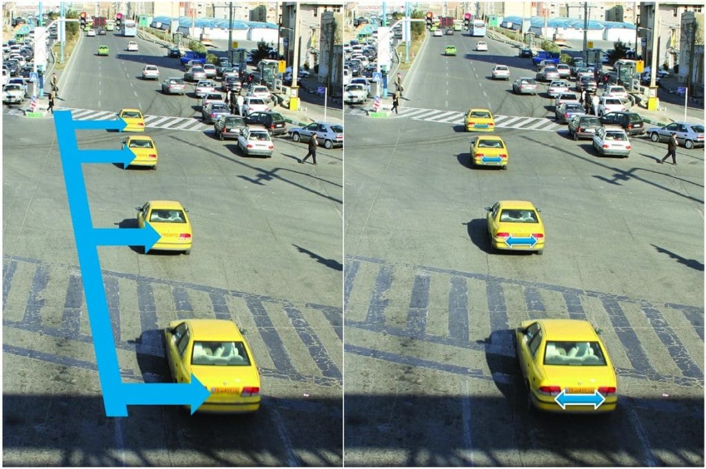
In this method the first thing to do is to recognize the body in the picture, so its location will be clearly defined. Since this picture is a two dimensional identity, detecting the object’s location needs finding the connecting line between camera and body in the 3-D space, so that the junction point of this line and ground line shows the objects location. Generally, we have:
.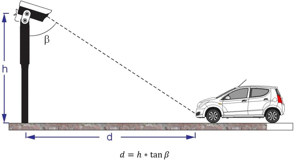
Thus, knowing h and measuring β, by processing the camera’s image and also knowing the camera’s setup angle, d can be calculated which is body's distance on the ground from the pole and its changes over time indicates body's Speed.
But as simple as this problem is, there are some hidden assumptions in it which not satisfying any of them will affect the output. We have supposed that:
- The exact camera’s setup angle is known
- The accurate height of the body from the ground is known
- The street is flat
Camera setup angle changing problem:
The camera can be fixed rigidly enough and if we utilize enough knowledge in instrumentation and image processing we would be able to measure the exact fixed setup angle, but this angle is likely to change after some time due to mechanical reasons such as:
- Foundation subsidence
- Expansions and contractions of the pole
- Joints wearing out
- The pole vibration because of strong winds and crossing heavy vehicles
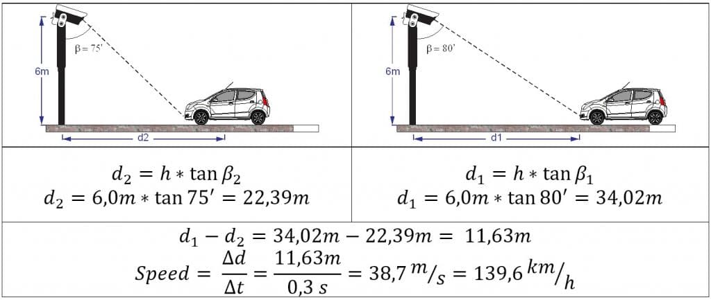
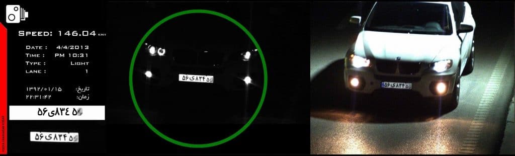
And that's where the difference between assumed angle and the real angle (that is changed over time) would cause inaccuracies in system. In fact, any vertical deviation in camera's angle directly affects the amount of β, and changes it. To calculate the amount of this error we suppose that we've got 2 pictures of a car, in a 0.3 sec time period: in the first one β=80°, the body is placed at a distance of 34 meters then the car approaches the camera (that is set on a 6-meter pole) so in the second picture β=75°, and it's placed at a distance of 22 meters. Therefore, the body's movement over this period is equivalent to 11.6 meters car travel down the road in our 3-D world. And if It lasted for 0.3 sec, the car's speed will be calculated about 38.7 m/s or 139 km/h. (Notice: in this example the numbers are chosen in a way close to the reality of speedometer cameras)
But let's imagine that our primary fixed angle has been changed or even it was measured incorrectly from the beginning, so the junction point of the ground line and the connecting line between camera and body is showing another point in 3-D space which is not its real location.
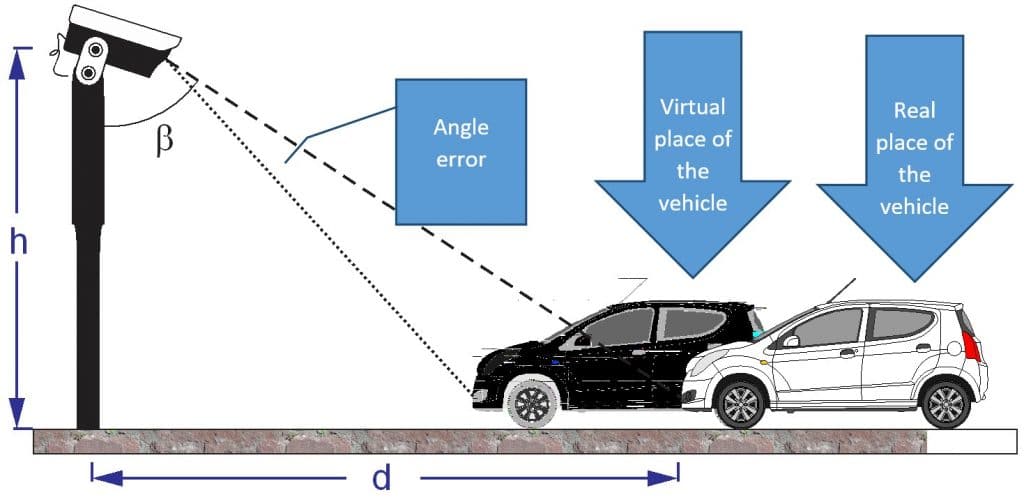
Now we suppose that the difference in angles is only about 0.5°, let's see how much the error would be in the calculated speed of the car:
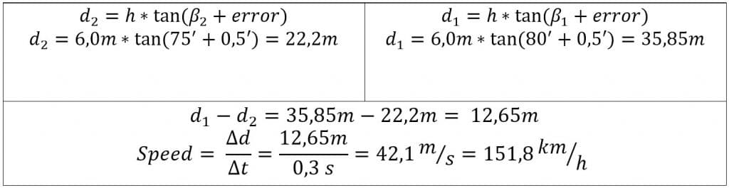
It can be seen that only a 0.5 degree of displacement in camera’s angle caused an increase from 139 km/h to 151 km/h in the vehicle’s speed which equals to an error more than 8% in speedometer. It is interesting that the error grows nonlinearly with angular displacement of the camera such that the error will be more than 18% due to only 1 degree of displacement.
Object’s height problem:
A parameter with length dimension was needed in order to create the triangle to determine the location of the body; hence the height of triangle was used. However, the important issue is that which point on the vehicle is chosen to be the characteristic point of the car and also what the value of h for that point is.
Different height of calculating point, if the license plate or the common border between car and the ground be considered as the characteristic point
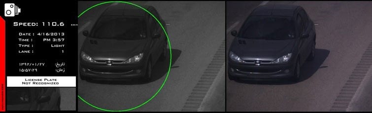
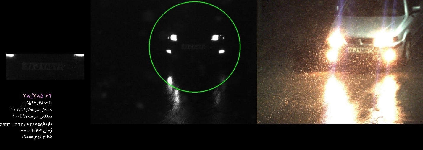
In order to find the characteristic point of the vehicle we do not have more than two options. The First one is to detect the car itself and then using the border of its body and the ground. The second is to use the license plate coordinates as the characteristic point for the whole car. Although in the first choice, h (the height of the camera pole from the ground) can be used as length parameter but specifying precisely the common border between car and ground and having it constant in different frames taken as the vehicle moves, is an important issue which is not always feasible in every light conditions and all day long. For example, during nights, especially on wet asphalt, a wave of light comes in before the car enters to the frame; so when the car gets in, only the license plate and headlights of the car are clear in the infra-red camera, and consequently there is no border detectable between car and the ground. This problem is not specifically for nights, this effect is also noticeable in many other light conditions such as shadows and cloudy weather. As a result, this method cannot be utilized as a practical approach on which a stable algorithm could be based on it. (It is worth mentioning that a minimum level of appropriate performance of a system must be necessarily tested and applicable in all different conditions.)
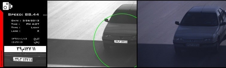
The border between earth and the vehicle is not clear in nights and the light condition is inappropriate
Second choice will be using the license plate coordinates as characteristic point of the vehicle. Here we face the fact that not all the license plates are installed at the same height. So difference between plates’ height will be a source of error. Also in this method it is necessary for the system to find the correct position of the license plate. And thus if the plate were mistaken (for example a writing on the car can be seen as the license plate) or system was not able to locate it (no software is as powerful as human eyes in reading license plates in every condition) then there will possibility be an error in performance or even no output.
Roads flatness problem:
It is fundamentally supposed that the road is flat and without curve In formation of the triangle. Obviously the system designed on this basis can have appropriate performance on totally flat roads only. In other words, the junction point of connecting line between the object and the curved road will be lower or higher than the balance line, which in turn causes error in locating the object and consequently in the speedometer.
Three problems mentioned for mono-cam image processing using triangle method are the major problems specified to this method. While it is possible to suggest some solutions like marking up the streets, but these solutions cannot be helpful in different times of the day or all kinds of weather, light and traffic conditions. Also they will increase the installing and calibration cost of the system such that the final system won’t be applicable in large scale projects and no extra daily repairing and resetting cost can be devoted. Nothing is more dangerous than the fact that all driving fines sent out by it cannot be absolutely accurate and reliable.
Mono-cam image processing Image size variation approach
As we mentioned before, we need a parameter with length dimension (m) in image processing and in this method the parameter will be Iran standard license plate dimensions (51 centimeters length and 11 centimeters height). So when vehicle approaches from far distance toward the camera, the size of plate will increase. Since the actual size of the plate is constant in real 3-D world, this increase in image size is due to changes in distance of the car which can be calculated by knowing the characteristics of the camera and the license plate (image processing of the license plate size in depth image of the object). Relationships describing this issue can be written as follows:
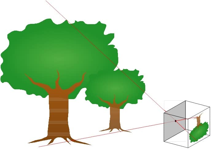
The role of the camera is to image all the bodies in the outer world into the picture’s plane. The picture below simply shows what a camera does:
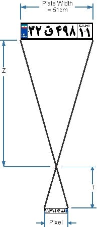
As we can see, a 51 centimeter license plate which is at a distance of z from the camera with f as focal length is imaged into a number of pixels. As shown in the above picture one can write the following equation for the camera:
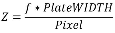
In the above equation f is the focal length of the camera lens, which is a constant number, and it is calculated upon the resolution and the type of lens itself. The Plate Width parameter is Iran's standard license plate width, which is 51 cm. Pixel variable is the number of width of the plate in the digital picture which comes from the image processing phase. Finally, Z is the distance of the vehicle from the camera which its changes determine the speed of the car.
As a numerical example, let’s consider there are two frames of a car where plate width is 150 pixels in the first one and 100 pixels in the second one. The time difference between these two is 0.3 seconds, thus we will have:
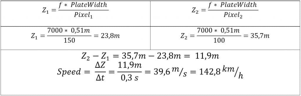
The main source of error in this method is the amount of plate width parameter coming from image processing in which we need to have the car’s license plate read in two frames and the plate’s width must be calculated in pixels for both images, whereas image processing is a fuzzy science in which there are always some errors. For example, suppose two last digits in the plate’s zone were 22 but they were misread as 23. Consequently, there will be some error in plate’s width. Even if the plate were read correctly still detecting the borders of the license plate and counting the number of pixels can be different from the actual one.
As a practical approximation it is absolutely usual to have up to 2 pixels error or even more errors in special conditions.
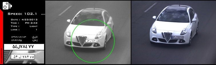
(Example of a real license plate from a speedometer camera in which the border of the plate is not as accurate as every single pixel.)
In order to calculate the error, suppose in one frame we have a 2-pixel decrease in plate’s width and a 2-pixel increase in the other frame. Thus the calculations are as follows:
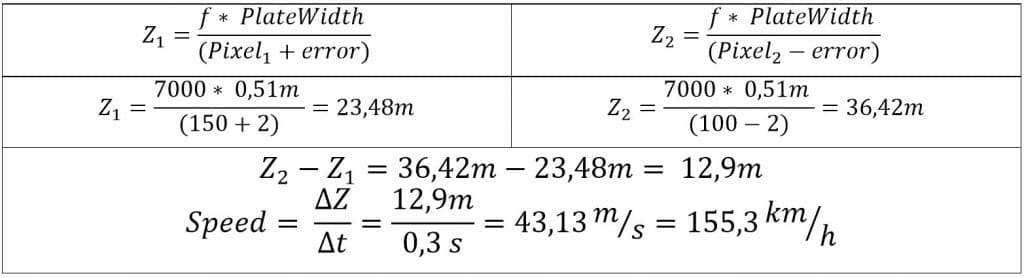
As we can see, a 2-pixel error in width of the license plate results the speed to change from 142 km/h to 155 km/h which is equivalent to more than 8% error in speedometer. It is worth to mention that the final error grows non-linearly with any increase in the number of error pixels. And 3-pixel error in width of the plate is equivalent to 13% error in total.
Mono-cam image processing general problems
We reviewed the Error calculations and intrinsic problems of both methods based on mono-cam image processing. Yet in addition to mentioned problems specified to each method, there are some general problems along with mono-cam image processing.
Integrating car detection and speedometer with ANPR:
Due to accurate specification of the characteristic point of the vehicle in “trigonometric” method and “size variation” method because of fundamental role of the license plate, the algorithms are depended on LPR process. That’s why no NPR core has through performance and has got some Errors like:
- Not detecting the license plate
- Mistaking a part of image or a script in it as license plate
- Error in reading numbers and plate scripts
That’s how the final result of the system in detecting the vehicles and exploitation of cars is affected by the performance of the LPR core. Naturally in systems based on ANPR not reading a license plate leads to invisibility of the vehicle to the system. Also considering some other parts of the image as plate due to any reason such as difference in height and plate size can bring in some unpredicted errors in the output speed. So the final system will have some weaknesses in two aspects:
- First of all, it won't perform powerfully in recording cars, and cars with unreadable plates (due to any reason like special plates, political or foreign plates, vehicles without license plate or manipulated plates) will be invisible to the system.
- Second, the ANPR errors which always are for granted (No one can acclaim that there is an error-proof plate reader, only if they put aside many suspicious cases which will result in loosing many cars in practice) will have adverse effects on the speedometer results and will expose the system to big case errors.
But if the vehicle detection phase were independent of LPR (being done by radar or stereovision), we can only expect the ANPR core to read the plates correctly in practice. And in case of failure, car detection and speedometer phases won’t be disturbed. Moreover, all cars owning any kind of plates or without plates can be identified and all the major operations of the system could be done without any problem.
Possibility of causing disorder in system by offenders (plate coverage):
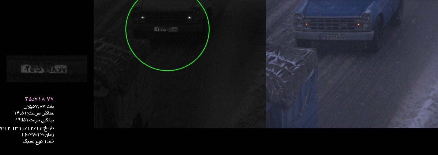
LPR based image processing can allow any delinquent to cover their plates, pass all the systems on the way with any speed and do any other violations then uncover it before approaching to a police station and in addition to speed violation, this person has done plate covering violation itself; which all have been hidden for the system. Systems in which the vehicle recognition and speedometer phase are separated from the LPR, can detect these cars, determine their speed and also send an alert of “No plate detected” in order to stop them in the next station.
A vehicle without its plate recognized by the stereovision system
Vehicle’s weight classification and moving lane detection problems:
As mentioned before, mono-cam vehicle recognition in any air, light and weather conditions is mainly based on LPR. We can never expect to distinguish accurately vehicle class and it’s moving lane, when all information available come from its license plate. For example, not all the license plates are installed in center.
Consider the situation in which the license plate is in the corners of the vehicle. Then it is possible for the vehicle to be mostly in the speed lane while it’s license plate is still in the middle lane. As another example, for a truck with no turned on front lights in night there is nothing recognizable in infrared camera but the license plate (the outlaw driver can learn to pass the cameras with turned off lights.), then in this situation the only thing to recognize the vehicle's weight class is the letter (ع) on the plate.
Low amount of data for vehicles:
Since the LPR camera needs a minimum number of pixels to read the digits on the plate, it is limited to the range in which it is possible to read the license plate and in distances more far than that, the plates are not readable because of small size of images. This fact bounds the rate of data for each car and consequently increases the possibility of occurring errors. Suppose a radar or image processing system in which the process of car detection starts form distance of more than 100 meters ahead, in this case our system has more time to collect information on location and speed of the subject in comparison with an LPR based system covering only 10-15 (a little more or less) meters ahead. In the first case we will obviously have more data which can help us to cancel out effect of one or two possible misreads of data by averaging or other numerical methods, that’s how error decreases due to high rate of data.
Plus, it is worth mentioning that LPR based systems have mostly lower frame rate compared to radar or stereovision systems which adds more deficiency to LPR based systems.
The problem of low rate of data in LPR based systems has other unfavorable effect on the results too. Generally, in these systems license plates are needed to be read in many frames (at least 2); while in systems where vehicle detection phase is separated from LPR, even one frame will be enough for a complete detection (Even if LPR process was not performed in that one frame, at least car detection and speedometer would be done). That’s why having thorough performance in LPR systems is harder than systems in which vehicle detection and LPR phase are independent. Because manifold plate reading must be done in LPR based systems but one plate being read is enough in independent systems.
This fact would be more important in higher speeds, where there is less time for license plate reading (so less frames). In other words, in practice it is more probable for LPR based systems to have lower performance in comparison to other systems in higher speeds.
In addition to speed and essential data for mathematical filters, optical and weather conditions, which are an essential for LPR based systems, also have great effect on multiple plates reading. Also they have unfavorable effects on the LPR process in bad weather conditions or direct sunlight; thus these situations will decrease the probability of good performance for LPR-based systems.
Solutions for mono-cam image processing problems
In previous sections some problems of mono-cam algorithms were introduced. But there are some known and general solutions to some of these problems. This in turn can fix them. In this section we tend to discuss these solutions’ limitations.
But first of all, an important point to consider is that using a color camera and an infrared one together never counts as double-cam image processing since they work in different color spaces and also they have no difference in point of views. So they are two different cameras that each one works as a mono-cam. Obviously the same reasoning applies to using several cameras, for each lane separately.
Marking up the road
Road surface marking is the most general solution to many deficiencies of mono-cam image processing. By measuring the marks on the road, camera’s displacement can be measured and almost corrected.
Even these signs can be used to get a better performance in curved paths or detecting vehicles with no license plate. But the important fact is that these signs are not expected to be found in the image correctly.
For example, following factors have significant effect on recognition of the signs:
Dark hours, when signs do not have proper infrared reflections like plates
Reflection from the plate’s surface is much more than any other thing in the image (due to the plate’s high reflection). Since cameras primarily tend to detect the plates, optical configuration of the camera is set according to the plates reflections, thus it is not expected for other bodies with lower reflection to be clear in a picture where plates are fully distinguished. Also at nights, before vehicle itself, a wave of light is seen in the picture which sometimes causes some pixels to change from completely dark state (zero) to completely bright state (255), marks are not expected to be recognized successfully in this light turbulence.
Path covered by rain water or snow such that signs are not visible
When running a project over a country with different air condition, one must always remember to design the system independent of detecting signs which can be covered by snow, road salt, etc.
Examples of outcomes of a speedometer system in practice, when the surface is not clear
Asphalt illuminated by direct sun radiation such that lines and signs are not visible
When setting up a system in country scale, even if we are the luckiest, there are always days in which sun shines in a direction which lights the roads surface completely (called over-exposure). In such a situation any script or sign on the road has the value of 255 just like the asphalt around it, and they all will be seen as completely bright pixels in the image.
Heavy traffic which vehicles cover the signs
In traffic jam, cars are too close to each other so that the asphalt between them is covered. Obviously no sign is expected to be observed.
Signs being covered by heavy vehicles
A passing heavy vehicle can cover the whole image such that nothing will be observable but the vehicle itself. Consequently, no mark is expected to be detectable.
Consider that a strong wind is blowing and the camera pole is trembling. (It was shown that even 0.5 degree of change in angle can be disastrous). At the same time one of above-mentioned factors have happened or even worse consider there had been snowing for several days, so the road has been covered by snow and salt. Low temperature has contracted the camera pole and consequently changed the camera angle. In such a situation thorough performance cannot be expected. Not only system is not capable of vehicle detection, but also there is higher probability of excessive error in speedometer.
In addition to the practical issues, in terms of operational aspects, road surface marking is an extra process in installing and calibration of the systems which slows down the running procedure. Moreover, we need to manipulate and consequently block the road for a long period of time. Also marks will be deformed and displaced as heavy vehicles pass or sun shines, which again affects the systems performance also resonates the need of periodic calibration.
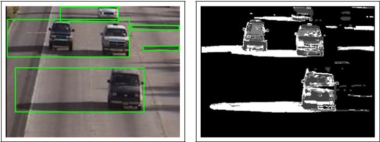
Motion Detection or Background Difference methods:
In addition to LPR, vehicle detection is also possible through methods of moving bodies’ recognition or forming background image and then calculating differences from background image. But these methods won’t be feasible in all weather and light conditions thus we cannot establish a reliable and permanent system based on them. For example, at nights before car coming into sight, its headlights send waves of light turbulence in the image which makes it impossible to use any of before mentioned algorithms. Besides direct sunshine, traffic jam, vehicles’ successive stopping and moving, shadow of trees in wind and many other phenomena make the usage of these methods impractical in stable and reliable systems.
Last sentence on mono-cam image processing method
Any speedometer system from any manufacturer needs an imaging camera and a license plate reader. Therefore, adding any module other than LPR module will increase additional cost to the system. That’s why radar based or stereovision systems always lose in the competition of final price. An ANPR based system works in the first look; practically it records many violations and traffic in a way that no other system is capable.
In practice, one problem is that testing and maintenance of the system is not taken seriously. Even the crucial science to test and maintenance of the system is not found in some projects in different places of the country. This problem has led to situation in which either system with any quality would be accepted and the contractor would be paid for it or the contractor becomes responsible for testing the system and the testing method would be required. Because of this problem unfortunately we have systems in which some regulatory cameras are defined as LPR and violence recorder systems in the country or only because the plates are readable in the pictures the camera is sold as LPR.
In addition to before mentioned, mono-cam image processing problems are generally revealed by time being passed and in special conditions such that accurate system evaluation need lots of time and also evaluation in different conditions as plates, day and night, weather and also technical setup state of the camera being covered.
LPR cameras regardless of marginal benefit being considered by executer companies are the economical answer in many circumstances:
- A cheap system with a proportionally good performance
- An acceptable range of error in speedometer so that no one will be punished for undone violence
- Detecting all the vehicles is not fatal to our system
- Short periods of maintenance and calibration of the system is accepted
Otherwise if we are looking for a serious system matching strict technical standards, for which number of undetected vehicles is really low and also the case and average error of speedometer is slight and simultaneously the maintenance period is not short these systems are not suitable. Practically, there isn’t any known LPR based product with mono-cam technology defined for speedometer violence record in world. Major usages of these systems are:
- Statistical surveys
- Traffic measurements
- Event detection
- Cases in which mistakes won’t result in driving fines for guiltless drivers or missing a number of vehicles won’t disturb systems final performance.